D502/7D控制压缩机,管道,储气罐压力低压报警或停机


 产品分类 产品分类
站内搜索 友情链接
|
D502/7D控制压缩机,管道,储气罐压力低压报警或停机
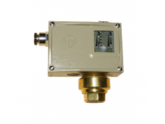
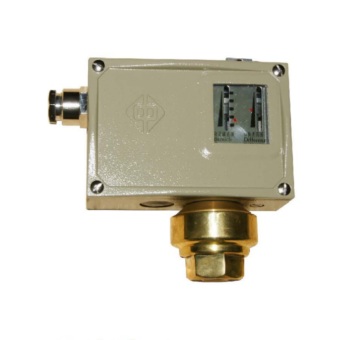
详细信息 D502/7D. D502/7DK
Pressure Switches
The pressure switches use bellows-type sensors.
Shanghai ZhongHe Automation Instrumentation co., LTD.
They can be used for neutral gases (such as air. Gas. water steam. etc) and liquid medium (such water. refrigerants. oil. etc) The set point of the pressure switch is adjustable. The adjustable range of set point is -0.1—4MPa.
□ Main Technical Data
Working Viscosity:<1×10⁻³m2/s.
switching Element: micro-switch.
Housing Protection Grade: IP65 (Accord with DIN40050 and corresponding to IP65 in GB4208)
Ambient Temperature: -40 ~ +50℃.
Medium Temperature: 0 ~ +120℃.
Vibration Resistance: D502/7D:40m/s2; D502/7DK:20m/s2.
Repeatability error: ≤1%.
Contactor Capacity: AC 220V 6A (reaistance)
(as for special requirements, you may refer to the Application Manual written by this factory)
□ Features
Suitable for vacuum
Action procedure of the single-pole double throw micro-switch:
The connecting terminals 1-3 will be connected when the pressure rises to the upper limit of the switching value; and the connecting terminals 1-2 will be disconnected when the pressure rises to the upper limit of the switching value.
□ Specifications (D502/7D)
·Switching Difference is Non-adjustable:
Adjustable Range of Set point
MPa
Switching Difference
(Not Ureatar Than)
Max. Allow-able Press-ure*
MPa
Number of Switch-ing Cycles
1/min
Pressure Sensor Materials
Processs-ing Connecti-on (External Thread)
Weight
Kg
Outline Dimen-sions (Drawing Number)
Order Number
Lower Limit of Set Point range
MPa
Upper Limit of Set Point range
MPa
Housing
Bellows
-0.1~0
-0.1~0.1
-0.1~0.16
-0.1~0.25
0.006
0.007
0.008
0.009
0.007
0.008
0.009
0.012
1
1
1
1
20
Brass
Stainese steel
00Gr17
Ni14
Mo2
(316L)
G1/4
G1/4
G1/4
G1/4
1.0
1.0
1.0
1.0
01
01
01
01
0810100
0810200
0810300
0810400
0~0.1
0~0.16
0~0.25
0.007
0.008
0.009
0.008
0.009
0.01
1
1
1
G1/4
G1/4
G1/4
1.0
1.0
1.0
01
01
01
0811100
0811200
0811300
0.02~0.4
0.03~0.6
0.03~1
0.03
0.03
0.03
0.03
0.035
0.04
2
2
2
G1/4
G1/4
G1/4
0.85
0.85
0.85
02
02
02
0811400
0811500
0811600
0.05~1.6
0.05~4
0.07
0.07
0.08
0.09
5
5
G1/4
G1/4
0.9
0.9
03
03
0811700
0811800
·Switching Difference is adjustable: (D502/7D)
Adjustable Range of Set point
MPa
Switching Difference
(Not Ureatar Than)
Max. Allow-able Press-ure*
MPa
Number of Switch-ing Cycles
1/min
Pressure Sensor Materials
Processs-ing Connecti-on (External Thread)
Weight
Kg
Outline Dimen-sions (Drawing Number)
Order Number
Lower Limit of Set Point range
MPa
Upper Limit of Set Point range
MPa
Housing
Bellows
-0.1~0
-0.1~0.1
-0.1~0.16
-0.1~0.25
0.018~0.08
0.019~0.1
0.02~0.2
0.022~0.25
0.019~0.08
0.021~0.1
0.022~0.2
0.024~0.25
1
1
1
1
20
Brass
Stainese steel
00Gr17
Ni14
Mo2
(316L)
G1/4
G1/4
G1/4
G1/4
1.05
1.05
1.05
1.05
01
01
01
01
0800100
0800200
0800300
0800400
0~0.1
0~0.16
0~0.25
0.015~0.08
0.018~0.1
0.02~0.2
0.016~0.08
0.02~0.1
0.024~0.2
1
1
1
G1/4
G1/4
G1/4
1.05
1.05
1.05
01
01
01
0801100
0801200
0801300
0.02~0.4
0.03~0.6
0.03~1
0.08~0.25
0.08~0.5
0.09~0.8
0.08~0.25
0.09~0.5
0.1~0.8
2
2
2
G1/4
G1/4
G1/4
0.9
0.9
0.9
02
02
02
0801400
0801500
0801600
0.05~1.6
0.05~4
0.17~1.2
0.18~2
0.19~1.2
0.2~2
5
5
G1/4
G1/4
0.95
0.95
03
03
0801700
0801800
□ Switch selecion and Mounting Instructions
·When selecting a pressure switch, it is recommended that the expected set point can be in middle area of the Adjustable Range of Set Point of the switch; and usually, this area covers 20%-80% of the adjustable range.
·When the switch is installed outdoors, sufficient protection should be provided, so as to avoid the violent change of environmental temperature, the direct radiation of sun-light, and the penetratin of corrosive gas or water.
·When installing the cable, suitable outside diameter of cable should be selected. The holding-down nut located at the position wher the cable has been led in should be tightened, so as to prevent the cablefrom being slack, as well as to avoid the penetration of water or dust.
·As for the controlled liquid dielectric having a pressure peak and pulsed pressure, a pressure shock damper can be mounted on the connector of the switch, so as to eliminate the unfavourable affection.
·the on-off current can not exceed the rated value.
·When installing (or removing) the switch, special attention should be paid to the following points:
In installation (or removing), the plane part of the sensor must be clamped down by use of a wrench, so as to absolutely prevent the sensor and the switch housing from rotating relatively to each other. (As shown in the following diagram).
The deepness for which the pipe connector is screwed into the sensor should not exceed 12mm.
共0条 相关评论 |